Wind load analysis and design and application of wind-resistant device for inverted construction of large storage tank
Time:
2022-11-22
Contents
Chapter I Preface 3
Chapter II Analysis and Calculation 3
Chapter III Conclusion 8
Chapter I Preface
In the construction of the tank or water tank inverted method, the first consideration is the safety problem, with the focus on the hydraulic lifting of the tank body and the wind load stress during the lifting process. The project implementation site is located in the coastal zone of Hong Kong, which is a windy area. During the construction process, strong winds of magnitude 7 and 8 are often encountered, and there are more typhoons every year. In the process of construction and lifting of tank body, strong wind will bring great safety hazards. Therefore, a large number of data have been consulted. Through the wind calculation during the tank lifting process, the wind resistance device of the tank has been designed, which is intended to be applied in the construction of the inverted tank method.
Chapter II Analysis and Calculation
1. Force analysis of transverse wind force on the tank body in the process of inverted hydraulic lifting
The inverted installation method is adopted for construction. The wind-resistant ring and reinforcing ring of the tank have been installed in place before lifting. The wind-resistant capacity of the tank body has met the design requirements, and the tank body will not lose stability and deformation. It is necessary to analyze the risk of overturning of the tank due to wind force during lifting. Here, take the dome roof tank as an example for analysis and calculation (wind force analysis when installing the bottom ring wall panel by inverted hydraulic lifting).
As shown in Figure 1, in the process of tank construction and lifting, the lateral force generated by the lateral wind on the tank body can be decomposed into torque M and lower lateral force P. The torque M and lower lateral force P are analyzed and calculated separately.
First, the design wind pressure is determined according to the Hong Kong 2004 Wind Operation Manual provided by the Buildings Department. According to the selection of design wind pressure changing with height, as shown in Table 1 (excerpt).
Height from ground/m
five
ten
twenty
Design wind pressure qz kPa
one point eight two
two point zero one
two point two three
Table 1 Design wind pressure altimeter qz
The process water tank is 13.39 m high, and the design wind pressure at this height is 2.085 kPa.
Average design wind pressure along height=[1.82 × 5+(1.82+2.01)÷2 × 5+(2.01+2.085)÷2 × 3.39]÷13.39 =1.913 kPa
In addition, according to the shape influence coefficient of the tank body, it is 0.75 according to the circle, then the tank body is stressed: transverse force P=35 m (diameter) × 13.39 m (total tank height) × 1.913 kPa × 0.75=672.4 kN (equivalent to 68.6 t).
Figure 1 Schematic diagram of wind force
Height of wind pressure acting point=5+(1.913-1.82) ÷ (2.01-1.82) × (10-5) =7.45 m
Considering that the wind resistance ring and other accessories of the tank are affected by the wind and the wind speed at the upper part of the tank is greater than the wind speed at the lower part, it can be considered that the stress point is 8 m high.
Torque M=68.6 t × 8 m=548.9 t/m
2.1 Stress analysis of torque M on tank body
When torque M acts on the tank body, the hydraulic cylinder on the windward side will bear the lifting force (the lifting force will decrease), and the hydraulic cylinder on the other side will bear the pressure (the lifting force will increase). As shown in Figure 1, the maximum stress position is point o of the hydraulic cylinder at the top of the leeward side of the tank body, and the stress value o α ; In order to simplify the calculation, the tank body is considered as a rigid body due to its cylindrical structure and large rigidity. The stress analysis is shown in Figure 1. The stress is linear, and the maximum value is o α'。
Only calculate o α' Value to system security, because o α'> o α , Actual stress o α It is also safe.
The diameter of the process water tank is 35 m, and 25 hydraulic cylinders are used for lifting. The hydraulic cylinder spacing is 4.34 m, and the circumference diameter of the hydraulic cylinder is 34.5 m.
Calculate the maximum stress of hydraulic cylinder o α' Value, according to
Where M is the wind torque; Fi is the force of hydraulic cylinder; Xi is the distance from Fi to the y-axis.
Taking the circumference of 1/4 tank wall as an example, we can think that there are infinite Fi, so the problem can be converted into integral form and solved by mathematical method: Xi=Rcos θ ; Fi is proportional to Xi, so Fi of an arc length can be expressed as
Fi=Rcos θ R δ d θ
Where δ Is the undetermined coefficient.
The maximum Fi, Fmax is at the x-axis, that is, the o point.
Fmax=o α'=δ· L·R=0.2267*548.9/17.25^3*4.34*17.25 =1.815 t
Where L is the hydraulic cylinder spacing.
According to the previous analysis, the actual maximum force is less than 1.815 t, the lifting force of the selected hydraulic cylinder is 25 t, and the lifting force of the single hydraulic cylinder is less than 17.25+1.815=19.065 t during the last circle of lifting installation, with sufficient safety margin (>20%). Torque M is not dangerous to the tank system.
1.2 Stress analysis of transverse force P on tank body
The inverted construction of water tank and storage tank has two construction sequences: first surround the lower wall plate and then lift the tank body, and then surround the lower wall plate.
The construction sequence of enclosing the lower wall panel first, and then lifting the tank body is adopted, because the lower wall panel and the limit plate welded at the upper end of the wall panel can bear the transverse wind force of the tank body and will not cause danger.
However, the construction sequence of enclosing the lower wall plate first and then lifting the tank body is adopted. The installation height of the wind-resistant ring and the reinforcing ring is high, which is not conducive to the use of automatic welding of the tank wall plate.
The construction sequence of lifting the tank body first and then enclosing the lower wall panel is adopted. The installation height of the wind-resistant ring and the reinforcing ring is only more than 1 m, and all the tank wall panel welds can be welded automatically. However, after the tank body is lifted, all the stress can only be borne by the hydraulic cylinder and the diagonal brace of the hydraulic cylinder. After testing and calculation, the double-stroke synchronous hydraulic cylinder of Beijing Changping Hydraulic Machinery Factory is selected. Under the maximum load bearing condition (the lifting height of the hydraulic cylinder is 2.5 m), the lateral bearing capacity of the hydraulic cylinder is only 1.5 t, which can not fully bear the lateral force. There are some hidden dangers, but only to ensure the installation accuracy, the following safety wind-resistant measures should be taken, and the system should have sufficient safety margin for the lateral wind load, The following is our plan to increase the wind resistance design and wind resistance measures according to the actual situation of the site.
2. Design principle and application of wind resistance device
The wind-resistant device includes diagonal brace and vertical rod. The lower end of the diagonal brace is hinged with the tank bottom plate, the upper end of the diagonal brace is hinged with the upper end of the vertical bar, the lower end of the vertical bar is hinged with the tank bottom plate, and the upper part of the vertical bar is installed with the inner side of the expansion ring. The design drawing is shown in Figure 2 and Figure 3.
Figure 2 Assembly design of wind resistance device
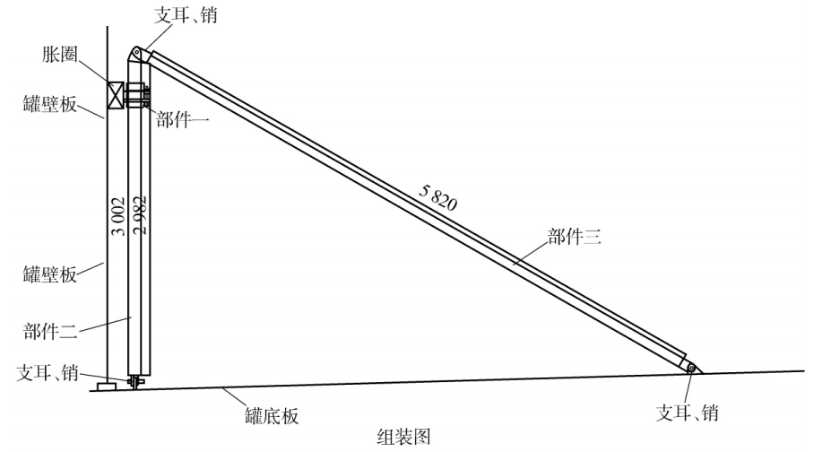
Figure 3 Component design of wind resistance device
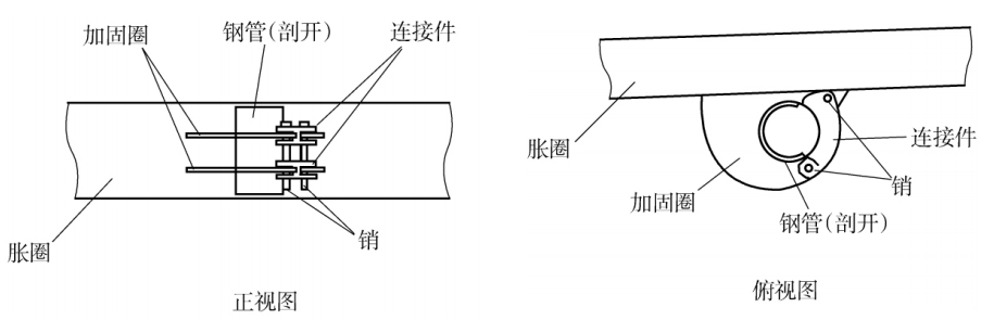
The wind-resistant device adopts hinged structure, and the first part adopts hinged opening, which fully considers the wind load bearing capacity and the convenience of installation and removal. The specific installation quantity of wind-resistant devices shall be determined according to the tank diameter, lifting height, maximum historical wind speed at the site and other factors, and shall be uniformly distributed along the inside of the tank during installation. For example, four are installed from the fourth round of lifting, increasing step by step, and the last round of lifting, increasing to 16.
Use requirements: the column (part II) shall be vertical when installed; After the lifting of the tank body is completed, or when the lifting stops in case of strong wind, insert square pins in the gap between the column and the upper protective pad of the expansion ring, at least two at each position, which are directly opposite to the two sides of the expansion ring, to ensure that the wind resistance device can effectively bear the load. The on-site installation of wind resistance device is shown in Figure 4 and Figure 5.
Figure 4 On-site safety object of wind resistance device
Figure 5 On-site safety object of wind resistance device (partial)
Chapter III Conclusion
1. The wind force analysis of inverted water tank construction is the key safety point of this technology. Especially in the coastal areas of Hong Kong, where there are many strong winds and even typhoons, the above anti-wind measures should be taken in particular during the construction. In case of extreme weather, the work should be stopped in time, and the evacuation can only be carried out after taking protective measures.
2. The project should establish a perfect weather early warning information mechanism and organization, calculate, analyze and rehearse the arrival time of gales and typhoons according to the satellite meteorological information of the Central Meteorological Station every month, and make early warning of gales and typhoons three days in advance every week, and take a series of anti-wind measures in advance.
3. After the commencement of the project, a detailed special wind prevention scheme shall be prepared, daily drills shall be conducted, and frequent reminders shall be made to ensure the safety of water tank construction.
4. The weather special plan for crane, welding and power use shall be prepared to ensure the safety during the lifting process of water tank construction and the quality and safety during welding and power use.
Related articles
Contact
Headquarter address: Floor 8, Shui'an International Office Building, Sanjiao Road, Heping Avenue, Wuchang District, Wuhan, Hubei Province
Factory address: Shuangliu Gulong Economic Development Zone, Yangluo District, Wuhan
Follow us
Quick navigation